 Рус
Рус
SOFTWARESoftware for vehicle MEMS IMU/GPS navigation system
PROGRAMS FOR PLATFORM INERTIAL NAVIGATION SYSTEMS
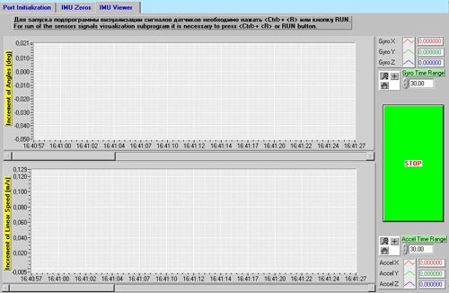
PROGRAMS FOR SYSTEM DEVELOPMENT, STUDY, AND DEBUGGING High-Accuracy Attitude Determination in Case of High-Frequency Angular Oscillations (Code: SO) Software for real time visualization of sensors output signals Software for real time visualization of sensors output signals Software for vehicle MEMS IMU/GPS navigation system
PROGRAMS FOR STRAPDOWN INERTIAL NAVIGATION
SYSTEMS (SINS) Calibration Calibration of a SINS Inertial Measurement Unit (IMU) Based on High-Accuracy Non-Mechanical Gyros Using Low-Accuracy Turntable (Code: SCLH) The program is designed to process SINS sensor data accumulated as a result of high-accuracy calibration of the IMU parameters (gyro drifts, accelerometer biases, accelerometer and gyro scale factors, accelerometer scale factor non-linearity, and sensor input axis misalignments). To do this, the IMU is to be turned in steps of 900(10 with respect to the local vertical and the north direction on a two-axis or three-axis turntable. The program is designed to determine the parameters of an IMU based on high-accuracy non-mechanical gyros (for example, laser gyros). Calibration of a SINS IMU Based on High-Accuracy Mechanical Gyros Using Low-Accuracy Turntable (Code: SCMH) The same as in Clause SCLH, except that the program is designed to determine the parameters of an IMU based on high-accuracy mechanical gyros (for example, high-accuracy dynamically-tuned gyros). Calibration of a SINS IMU Based on Low-Accuracy Non-Mechanical Gyros Using Low-Accuracy Turntable (Code: SCLL) The program is designed to process SINS sensor data accumulated as a result of high-accuracy calibration of the IMU parameters (gyro drifts, accelerometer biases, accelerometer and gyro scale factors, and sensor input axis misalignments). To do this, the IMU is to be turned in steps, at first, of 450(10' with respect to the local vertical, and, then, of 900(10 with respect to the local vertical and the north direction on a two-axis or three-axis turntable. The program is designed to determine the parameters of an IMU based on low-accuracy non-mechanical gyros (for example, fiber-optic gyros). Calibration of a SINS IMU Based on Low-Accuracy Mechanical Gyros Using Low-Accuracy Turntable (Code: SCML) The same as in Clause SCLL, except that the program is designed to determine the parameters of an IMU based on low-accuracy mechanical gyros (for example, low-accuracy dynamically-tuned gyros). Accelerometer Unit Calibration Using Low-Accuracy Turntable (Code: SCA) The program is designed to process accelerometer data accumulated as a result of accelerometer unit high-accuracy calibration (biases, scale factors, and input axis misalignments). To do this, the IMU is to be turned in steps of 450(10' with respect to the local vertical on a two-axis or three-axis turntable. Alignment Alignment on a Fixed Base (Code: SAF) The program performs algorithms designed to determine the IMU attitude with respect to the north direction and the local vertical line on a fixed base, as well as to calibrate some IMU parameters. Alignment on a Rocking Base (Code: SAR) The program performs algorithms designed to determine the IMU attitude with respect to the north direction and the local vertical line on a base that is performing angular and linear oscillations around/along two or three axes, as well as to calibrate some IMU parameters. Alignment on a Moving Base (Code: SAM) The program performs algorithms designed to determine the IMU attitude with respect to the north direction and the local vertical line on a base that is moving, as well as to calibrate some IMU parameters. Navigation Autonomous Aircraft Navigation (Code: SNAA) The program performs algorithms designed to determine the civil aircraft position, velocity, and attitude in the pure inertial mode. Autonomous Land Navigation (Code: SNAL) The program performs algorithms designed to determine the vehicle position, velocity, and attitude in the pure inertial mode. Integrated-System Land Navigation (Code: SNIL) The program performs algorithms designed to process jointly SINS sensor data and data from other sources (a satellite navigation system, an odometer, zero ground velocity during vehicle stays and stops, etc.). As a result of this, the accuracy of determination of the output parameters (position, velocity, attitude) improves considerably due to the correction of the system, as well as due to improvement of the IMU vertical and heading alignment and IMU parameters calibration. Integrated-System Aircraft Navigation (Code: SNIA) The program performs algorithms designed to process jointly SINS sensor data and data from other sources (a satellite navigation system, a Doppler velocity measurement system, altimeter, etc.). As a result of this, the accuracy of determination of the output parameters (position, velocity, attitude) improves considerably due to the correction of the system, as well as due to improvement of the IMU vertical and heading alignment and IMU parameters calibration. Simulation SINS Sensor Data Simulation for Calibration (Codes: SMC-LH, SMC-MH, SMC-LL, SMC-ML) The programs of the SMC series are designed to debug the SCLH, SCMH, SCLL, SCML sensor data processing programs and their algorithms, as well as to evaluate the accuracy of IMU parameter calibration using the Monte Carlo method. SINS Sensor Data Simulation for Alignment (Codes: SMA-F, SMA-R, SMA-M) The programs of the SMA series are designed to debug the SAF, SAR, and SAM alignment programs and their algorithms, as well as to evaluate the accuracy of alignment using the Monte Carlo method. SINS Sensor Data Simulation for Movement (Codes: SMN-AL, SMN-AA, SMN-IL и SMN-IA) The programs of the SMN series are designed to debug the SNAL, SNAA, SNIL, SNIA navigation programs and their algorithms, as well as to evaluate the accuracy of the system output parameters using the Monte Carlo method. Laser Gyro Output Pulse Simulation (Code: SMO) The program is designed to debug the SO program, as well as to evaluate the accuracy of attitude determination by the SO program algorithm. PROGRAMS FOR PLATFORM INERTIAL NAVIGATION SYSTEMS Calibration Calibration on a Fixed Base (Code: PCF) The program is designed to process sensor data accumulated as a result of calibration of the system parameters (gyro drifts, accelerometer biases, accelerometer scale factors, accelerometer input axis misalignments, platform gimbal axis misalignments) on a fixed base (in a laboratory or in a field environment) without using a turntable or any external data. Calibration on a Moving Base (Code: PCM) The program is designed to process sensor data accumulated as a result of calibration of the system parameters (gyro drifts, accelerometer biases, accelerometer scale factors) on a moving base. Platform Drift Case and Heading Effect Calibration (Code: PCD) The program makes it possible to determine the values of the platform horizontal drifts as a function of the system case position with respect to the north (heading effect) and of the platform internal gimbal position with respect to the system case (case effect) in order to compensate them at the time of system operation. Alignment Alignment on a Fixed Base (Code: PAF) The program performs algorithms designed to determine the platform attitude with respect to the north direction and the local vertical line on a fixed base, as well as to calibrate some system parameters. Alignment on a Rocking Base (Code: PAR) The program performs algorithms designed to determine the platform attitude with respect to the north direction and the local vertical line on a base that is performing angular and linear oscillations around/along two or three axes, as well as to calibrate some system parameters. Alignment on a Moving Base (Code: PAM) The program performs algorithms designed to determine the platform attitude with respect to the north direction and the local vertical line on a base that is moving, as well as to calibrate some system parameters. Navigation Autonomous Aircraft Navigation (Code: PNAA) The program performs algorithms designed to determine the civil aircraft position, velocity, and attitude in the pure inertial mode. Autonomous Land Navigation (Code: PNAL) The program performs algorithms designed to determine the vehicle position, velocity, and attitude in the pure inertial mode. Integrated-System Land Navigation (Code: PNIL) The program performs algorithms designed to process jointly inertial system sensor data and data from other sources (a satellite navigation system, an odometer, zero ground velocity during vehicle stays and stops, etc.). As a result of this, the accuracy of determination of the output parameters (position, velocity, attitude) improves considerably due to the correction of the system, as well as due to improvement of the platform vertical and heading alignment and system parameters calibration. Integrated-System Aircraft Navigation (Code: PNIA) The program performs algorithms designed to process jointly inertial system sensor data and data from other sources (a satellite navigation system, a Doppler velocity measurement system, altimeter, etc.). As a result of this, the accuracy of determination of the output parameters (position, velocity, attitude) improves considerably due to the correction of the system, as well as due to improvement of the platform vertical and heading alignment and system parameters calibration. Simulation System Sensor Data Simulation for Calibration (Codes: PMC-F, PMC-M and PMC-D) The programs of the PMC series are designed to debug the PCF, PCM, and PCD sensor data processing programs and their algorithms, as well as to evaluate the accuracy of system parameter calibration using the Monte Carlo method. System Sensor Data Simulation for Platform Alignment (Codes: PMA-F, PMA-R, and PMA-M) The programs of the PMA series are designed to debug the PAF, PAR, and PAM platform alignment programs and their algorithms, as well as to evaluate the accuracy of alignment using the Monte Carlo method. System Sensor Data Simulation for Movement (Codes: PMN-AL, PMN-AA, PMN-IL, and PMN-IA) The programs of the PMN series are designed to debug the PNAL, PNAA, PNIL, PNIA navigation programs and their algorithms, as well as to evaluate the accuracy of the system output parameters using the Monte Carlo method. PROGRAMS FOR SYSTEM DEVELOPMENT, STUDY, AND DEBUGGING Evaluation of the Accuracy of the Inertial System Output Parameters Based on the Accuracy of Its Gyros and Accelerometers and Specified Trajectory (Code: COV) The program is designed to determine the RMS errors of determination of the inertial system output parameters (position, velocity, attitude) based on the gyro and accelerometer accuracy and specified trajectory. The program is designed to study the navigation system characteristics and to substantiate the decision making process. L aser-Gyro IMU Design Optimization (Code: INF)
The program performs the algorithm that provides for the highest accuracy of attitude determination within a wide frequency range of angular oscillations. Part of the program may be performed in a simple digital machine, which makes it possible to reduce considerably the SINS central computer load. Software for real time visualization of sensors output signals
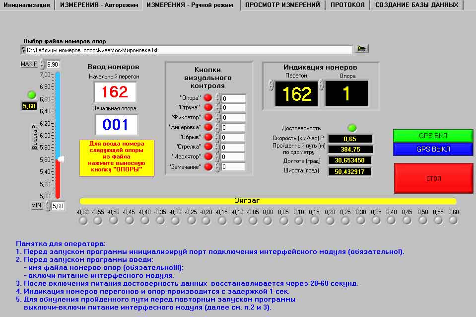
Railway contact-wire line control Software 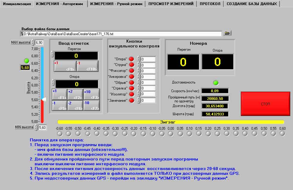

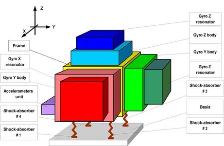
SINS IMU
High-Accuracy Calibration Using Low-Accuracy Turntable (Programs SCLH, SCMH, SCLL, SCLH)
|